This guide suits both version V1 and V2 of the standard (non-RGB) Sofle Keyboard. Most of the photos are for v1 and the differences are explained in the text as needed.
The RGB version has dedicated build guide.
The Choc version has dedicated build guide.
If you don’t have all the necessary parts, please read about how to source the parts.
Bill of materials
The following is needed to build the keyboard. You can find links for the most of the components in the sourcing parts section.
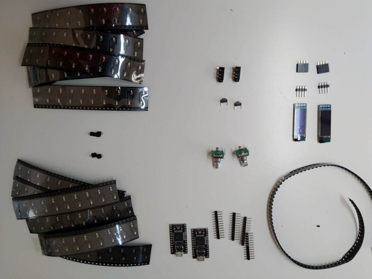
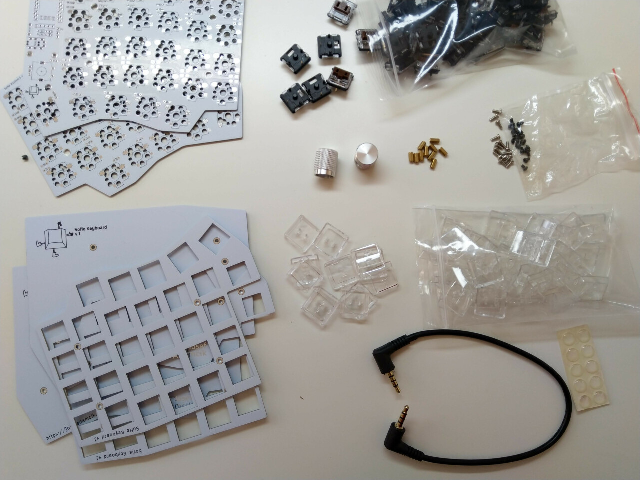
- 2 PCBs (see sourcing)
- 2 top plates, 2 bottom plates for a sandvich-case build. (see sourcing)
- 58 keyboard switch sockets by Kailh. The PCB supports either sockets for traditional MX switches or sockets for Kailh Choc switches. Note that version 2 supports only MX. They are available on Aliexpress, KBDFans and others.
- 58 keyboard switches of your preference, either MX or [Kailh Choc][choc]. Just make sure you have matching sockets for them. Note that version 2 supports only MX.
- 58 keycaps. You can use either all in
1usize but it looks nicer with two1.5ufor the thumb keys. - 58 diodes 1N4148W. They are surface mount diodes in SOD123 package.
- 2 TRRS connectors PJ-320A. The same type which is used for Corne, Lily58 etc. Technically even TRS should work1 if you stick to (default) serial communication.
- 2 tactile buttons through-hole, 2 pins. Technically optional: you can use metal tweezers whenever you need to reset the microcontroller. There’s also a reset key on default layout so as long as you have firmware flashed and working you shouldn’t need reset button on the board.
- 1 TRRS cable. TRS should work1 if you stick with Serial.
- 10 (+4) M2 spacers. 10 are going to hold the bottom and the top together. Their height depends on which switches you use. A build guide Lily58 Pro suggests
4mmfor Choc and7mmfor MX. I was not able to get7mm, but6mmworked well for me with MX switches. I used brass ones but you can also buy nicer from anodised aluminium. Another 4 would be needed to hold transparent OLED cover but even though there are mounting holes in the PCB. - 20 (+8) M2 screws. 20 are going to hold the boards together (via spacers). I used some I had in my stock so I am not going to tell you exact length. But they need to be long enough to fix a
1.6mmthick PCB to the spacer and short enough so two of them can fit in one spacer (might be trickier with 4mm spacers for Choc switches) - 8 - 10 adhesive rubber feet. They are really important, trust me.
- 2 ssd1306 128x32 OLED display module. Very common everywhere.
- 2 OLED covers Optional. OLED cover should be cut from transparent acrylic. Source file for version 1 is avalalble in the repostiory. There is no OLED cover for version 2 available yet.
- 2 Rotary encoders EC11, optional. So far I have used only one but 2 are supported. If you are not sure take EC11E. Some other variants (EC11K) may have some additional plastic pins for and require mounting holes for them (which are not included on the PCB).
- A matching knob for each encoder.
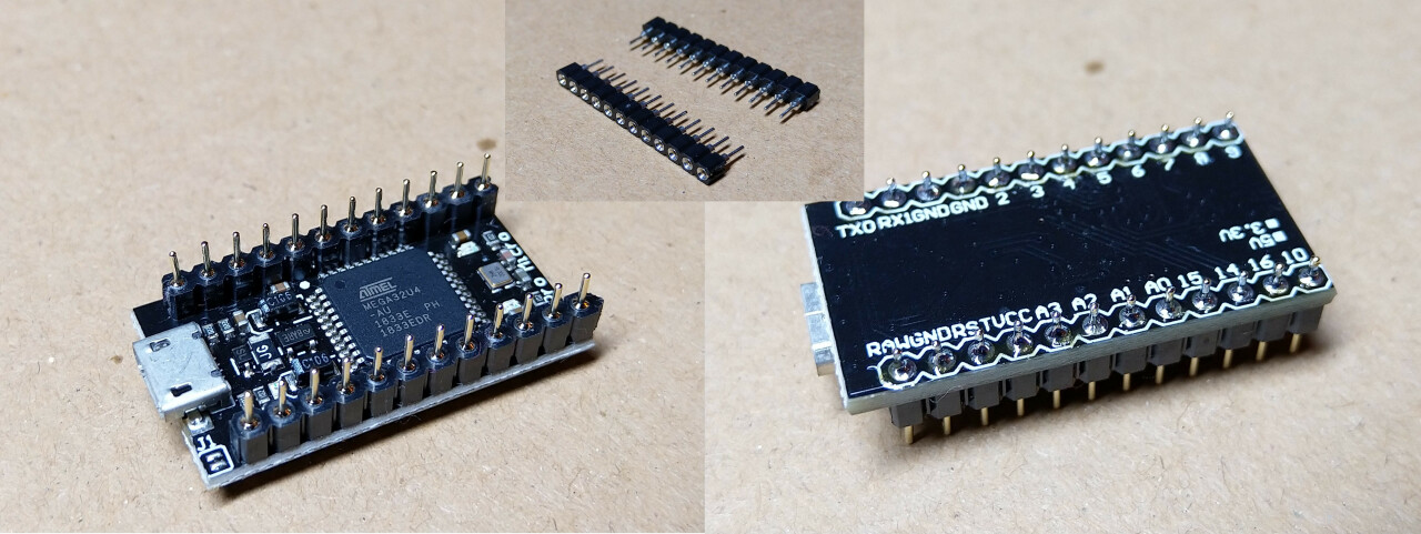
- 2 Pro Microboard or clone. With 2x12 pins and ATmega32U4 microcontroller. Just make sure you don’t buy something like Arduino Micro (a different pinout) or Arduino Mini (different microcontroller). You could also use Elite-C which basically Pro Micro with USB-C.
- 4x12 pin header (and optionally socket) for Pro Micros. There are several ways how to mount Pro Micros to the board. Either the male PIN headers you most likely got with the board from the supplier could be used to solder it directly to the board. Build guides for Helix, Corne and Lily58 suggest those spring pin headers which are very compact and give you non-permanent connection (you can remove or replace Pro Micros). Another possible approach is described at splitkb.com.
- 2x4 pin header (and optionally socket) for OLEDs. I have used the most common 1x4 female pin sockets which are quite tall but they also fit the height of ProMicro with the sockets I have used. Unfortunately, the pin headers on my OLED modules (again those very common square male headers you would get with the modules) are loose in the sockets. It works but it’s fiddly. I’ll have to find a better solution.
- Micro USB Cable to connect the keyboard to a computer.
That’s it. There are no RGB LEDs on the board. But if you really need underglow it is be possible to connect an RGB LED strip since there are 3 pads (VCC, GND and data) on the board. You would need to add support to the firmware on your own.
Tools and materials
- soldering iron
- solder
- good tweezers
- masking tape
- isopropyl-alcohol for cleaning
- screwdriver
Warnings and disclaimers
- Think twice, solder once. Desoldering is frustrating and it’s easy to mess up things.
- Don’t connect or disconnect the TRRS cable when the keyboard is powered. It may short out. Always disconnect the USB cable first.
- Be gentle with the USB on your microcontroller. They are easy to break.
- Keep in mind that this is a prototype of a DIY keyboard. It’s not a polished product.
Steps
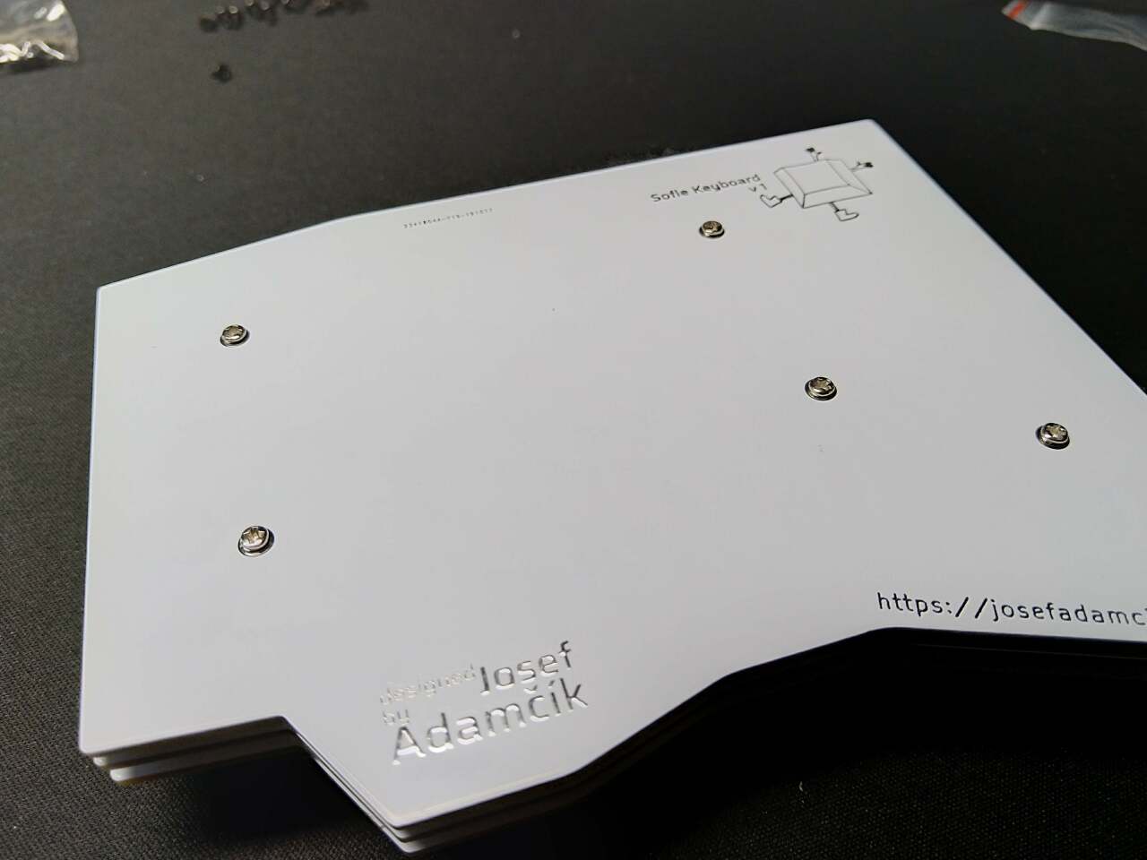
Prepare
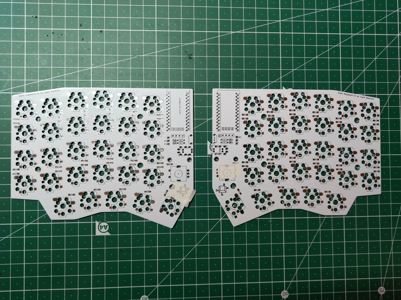
Both sides of the keyboard ready. The front sides marked by pieces of tape in order to remember which side is which.
Components on the backside
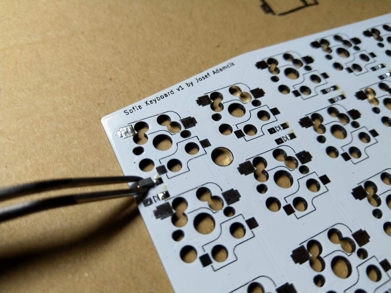
Starting with the diodes. They belong to the backside of the PCB. Make sure you have orientation right - they are all oriented to the same side. The end with the thin line is Cathode (-) and it should go in the direction of the “arrow” symbol on the PCB.
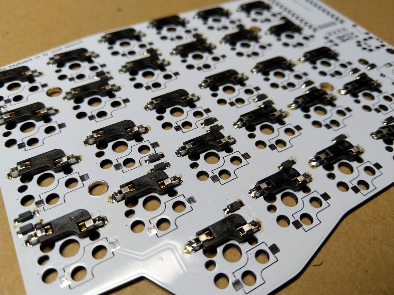
Sockets for switches belong again on the back side, the same side as diodes. Make sure they are flush with PCB. Watch the markings on the silkscreen which show the correct orientation.
Components on the front side
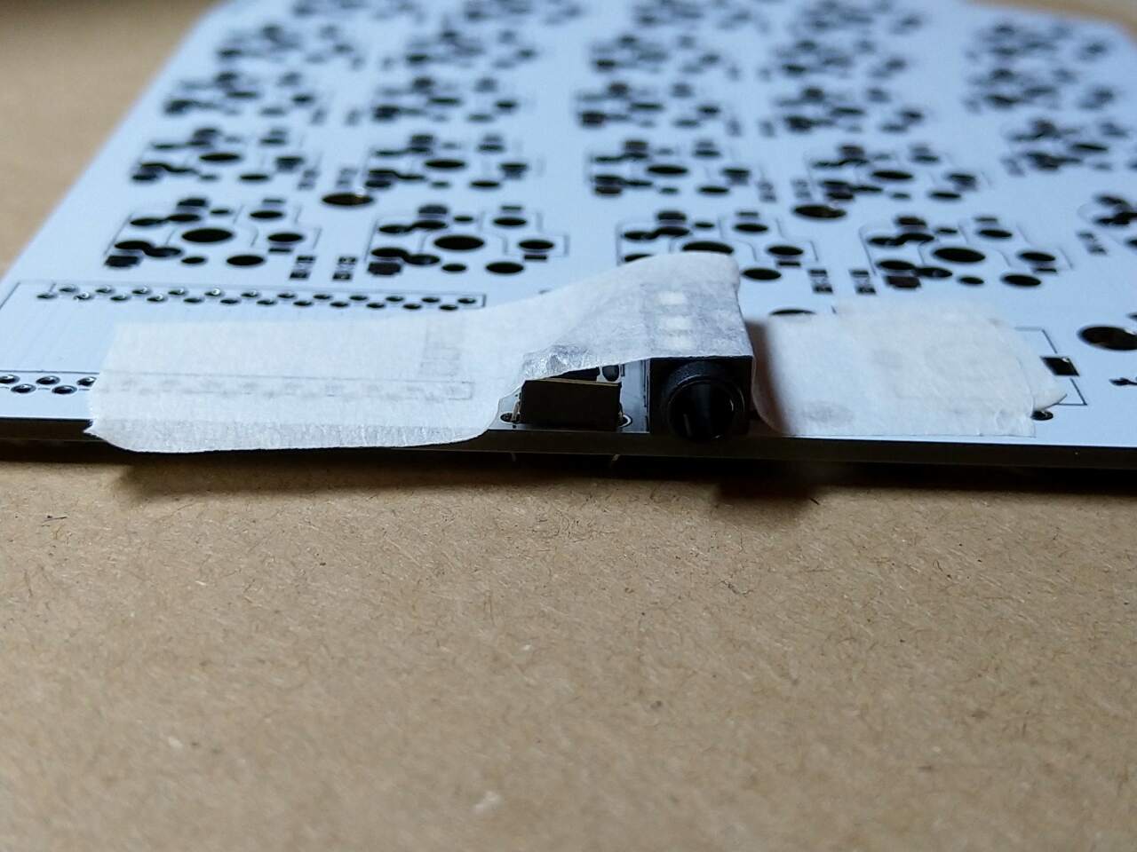
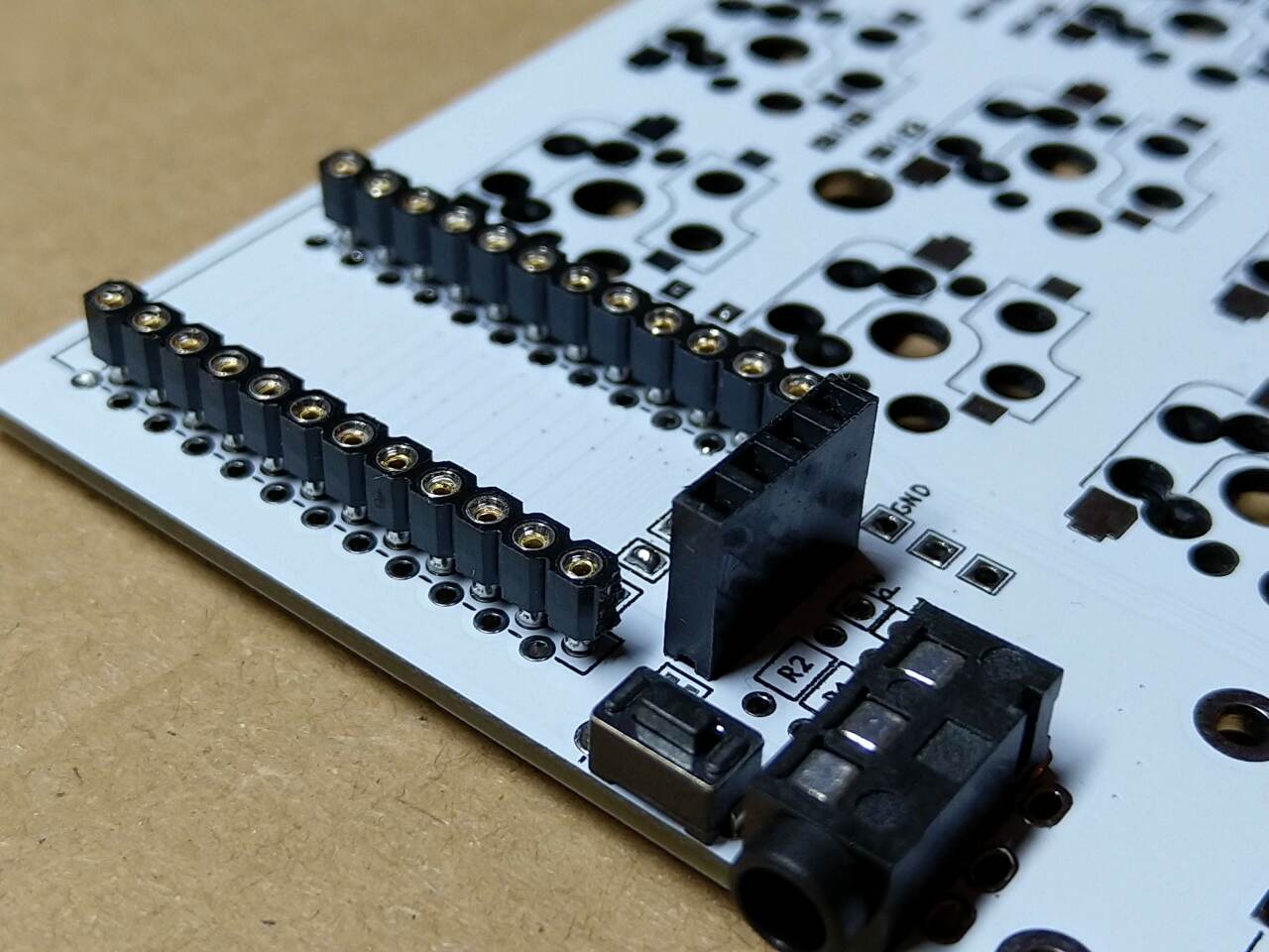
Button and TRRS sockets belong to the top. Use a piece of tape to fix them and apply solder from the bottom side.
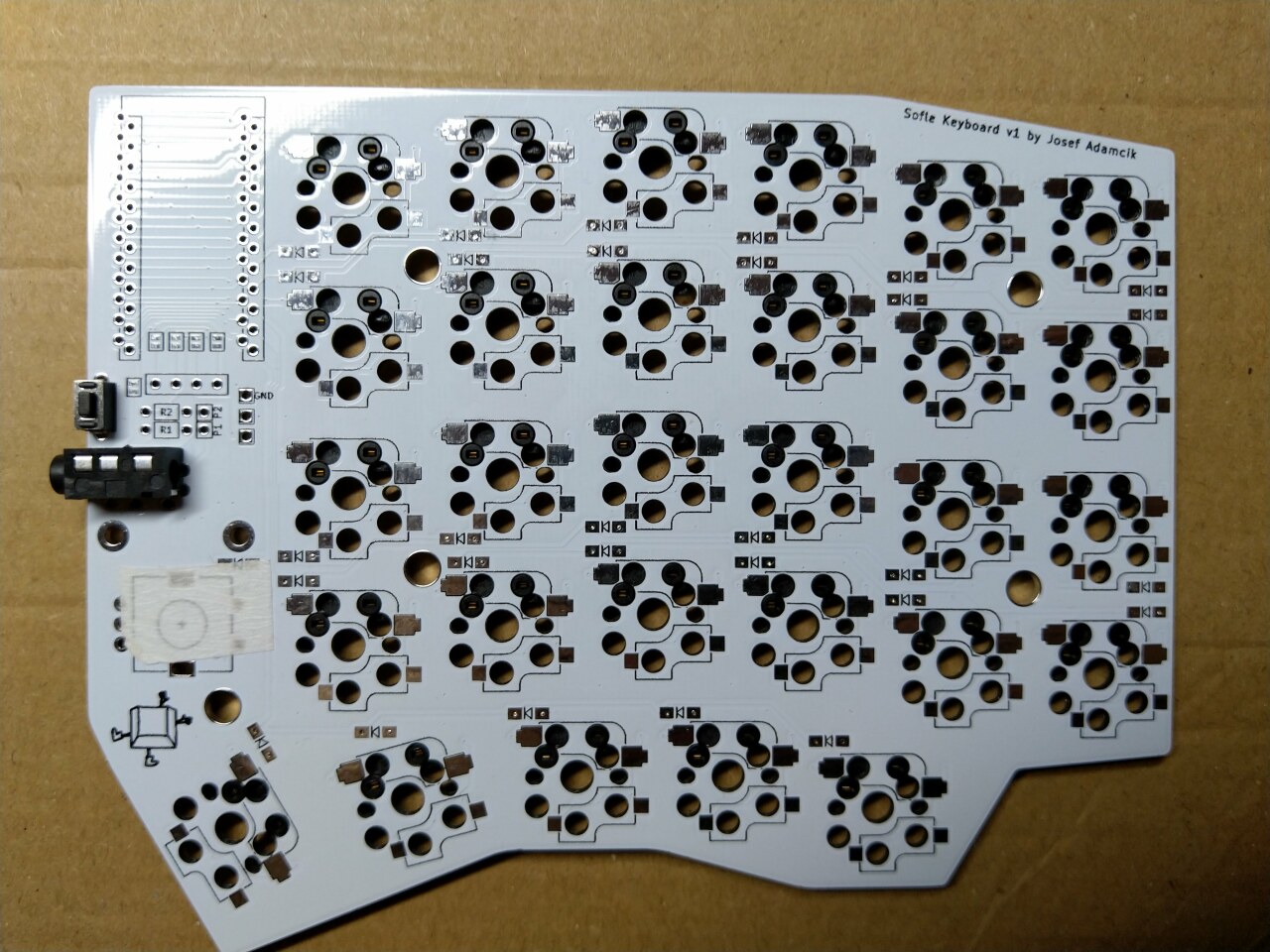
This is how the right half should look from the top.
Pro Micro and displays
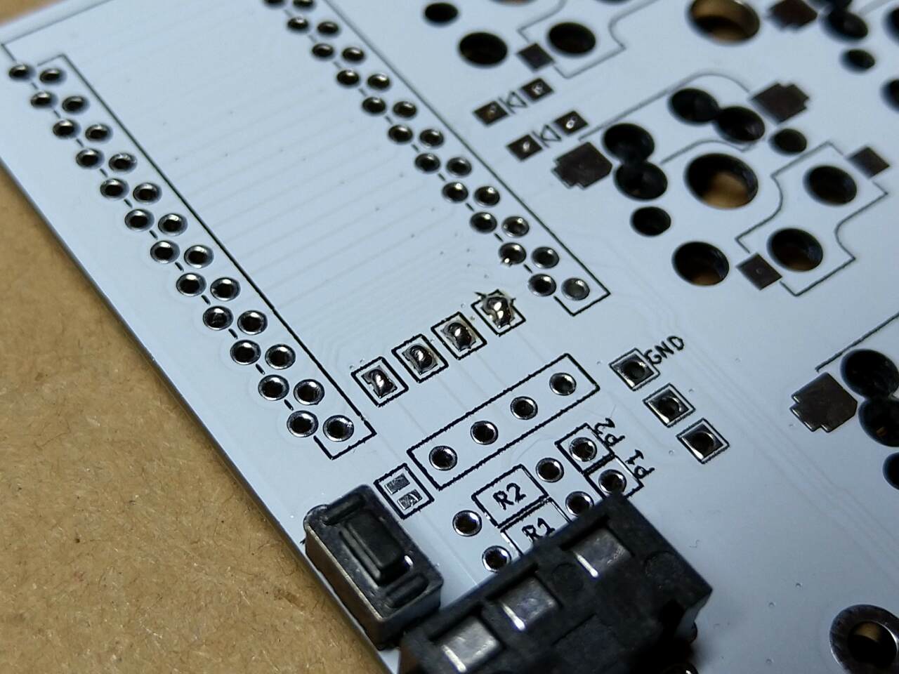
Bridge 4 jumper pads on the top side. They are necessary for OLED support and if you don’t socket you Pro Micro you will not be able to do it later.
Prepare the Pro Micro. There are several ways how to do it. I have used rounded pin headers. A bit more information about socketing of Pro Micro is on the sourcing parts page.
Keep in mind the orientation:
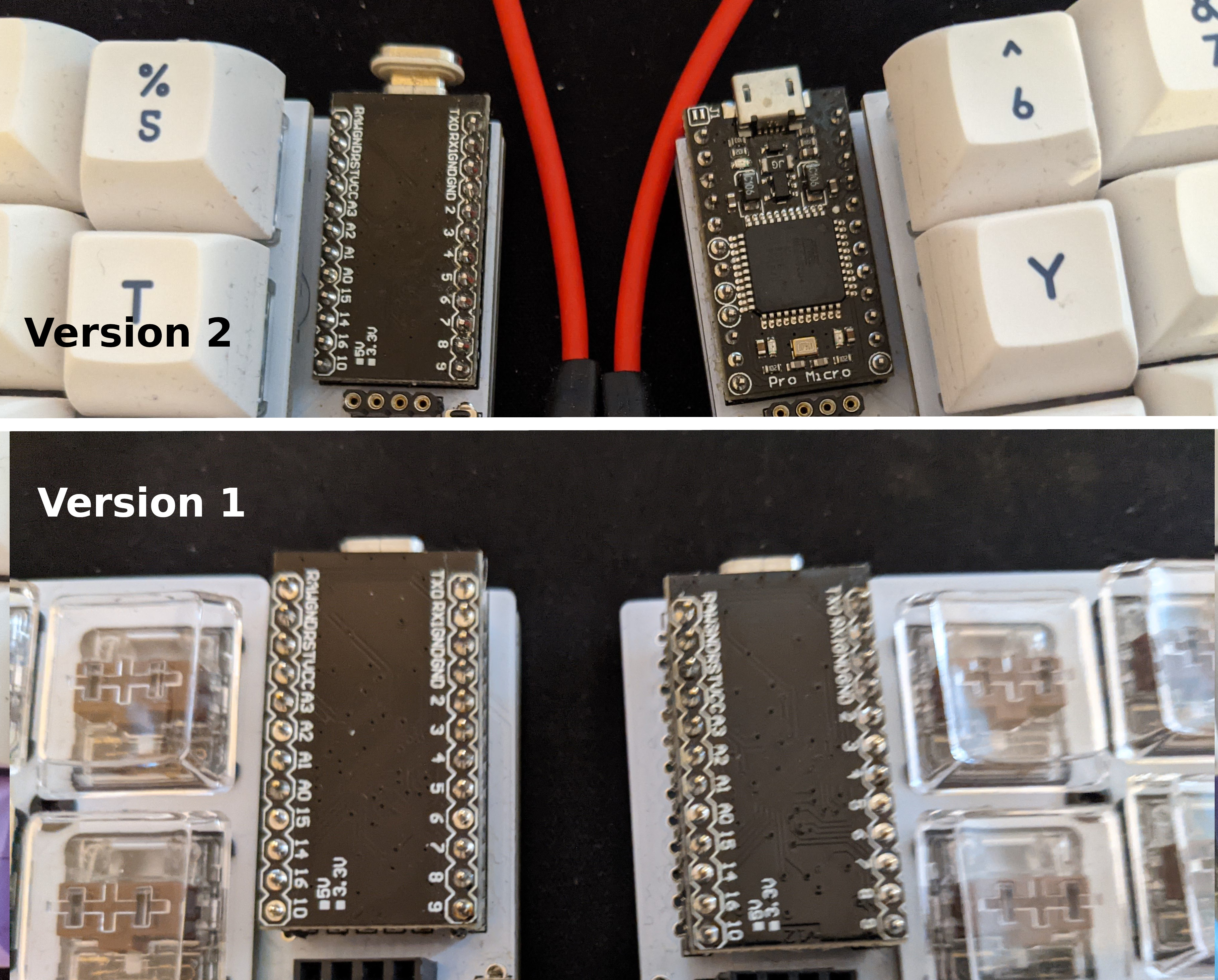
Version 1: the Pro Micro board should be mounted “bottom-up”. Its clean side should be at the top, visible. The side with chips and other electronics should be at the bottom facing the main PCB.
Version 2: The left side as for version 1. The right half has the pro micro mounted up-side up so it’s mounted differently on each half.
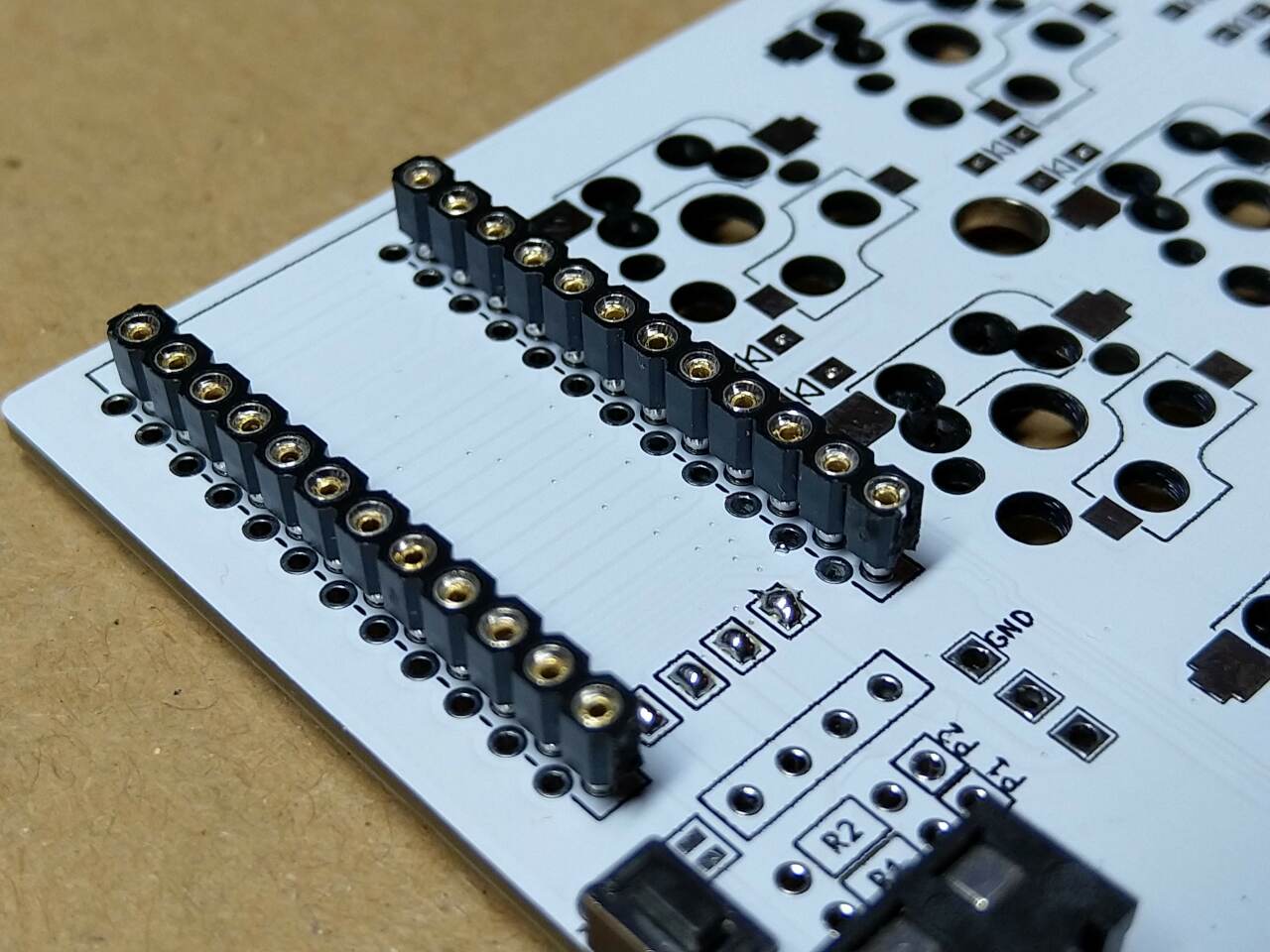
And corresponding sockets (if used) on the front side of the board. Version 1: Make sure you insert them into the holes which are marked by the rectangles. Version 2: there’s only one option so it is straightforward.
Add socket for OLED display. Keep in mind height of your Pro Micro which may be different based on if/which socket’s you have used for Pro Micro. Check everything before soldering.
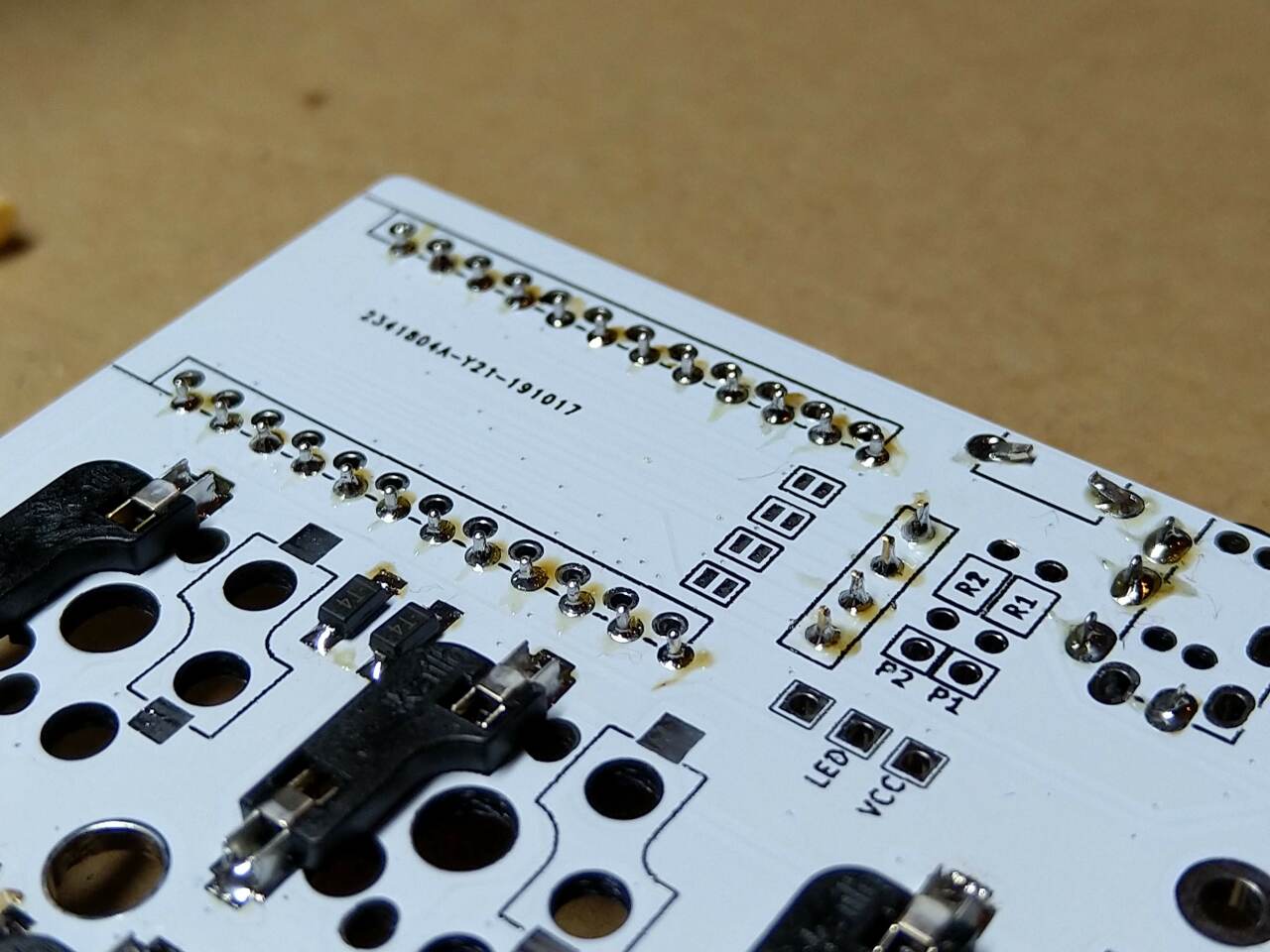
This is how the backside (bottom) should look at this stage.
First test
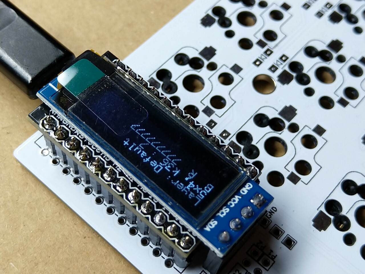
Now it is already possible to connect the ProMicro and OLED display to the board, flash the firmware and check if all keys work using a piece of wire or tweezers.
Rotary encoders
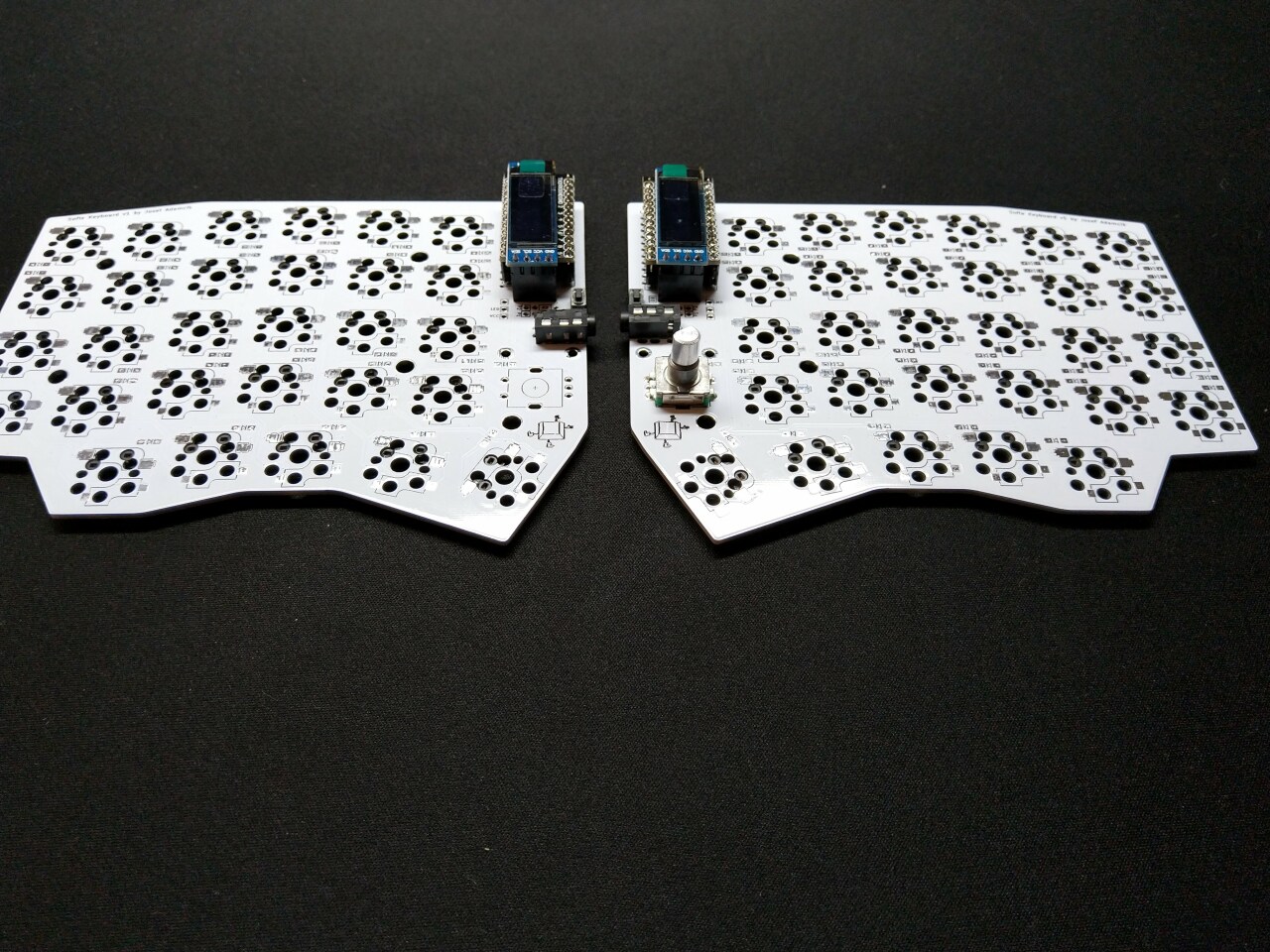
Both halves assembled, a rotary encoder can be added on both, one or none. I have also cleaned flux residue from the back side using some isopropyl alcohol, cotton buds and paper towels.
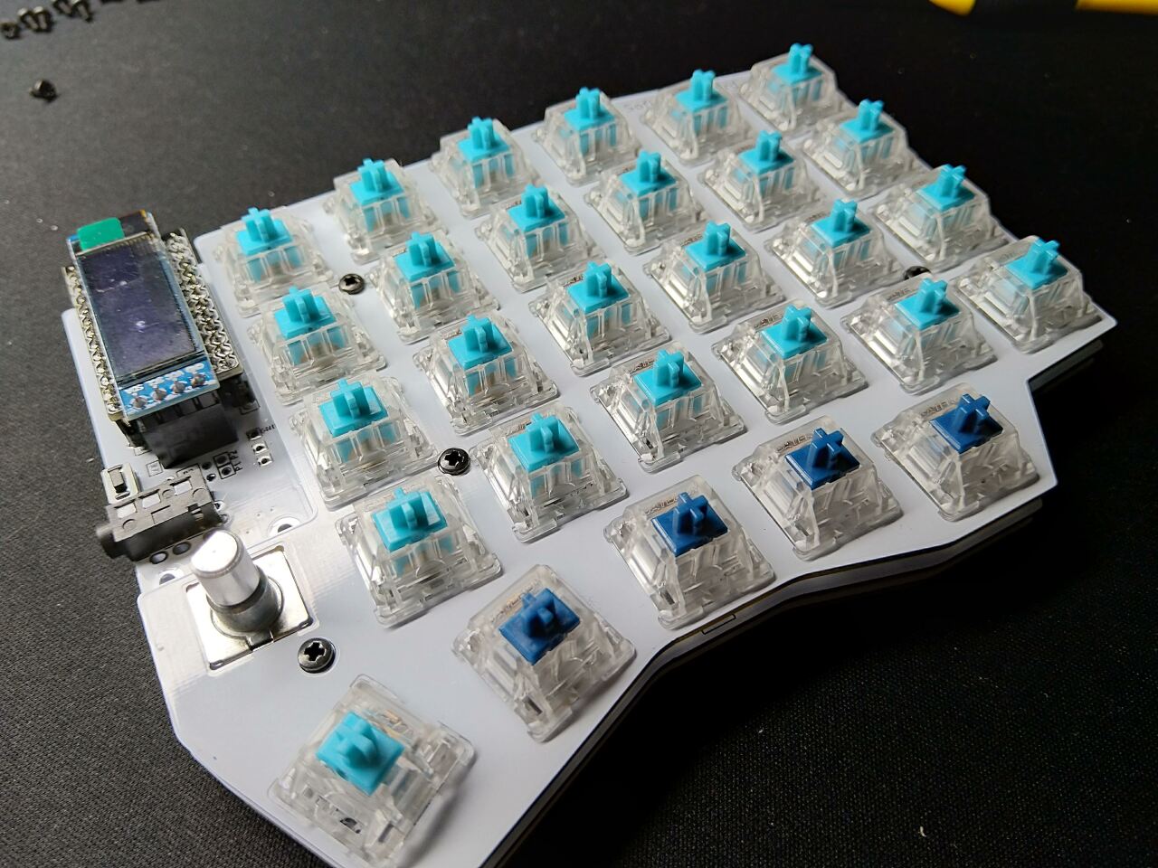
Keyboard switches and plates
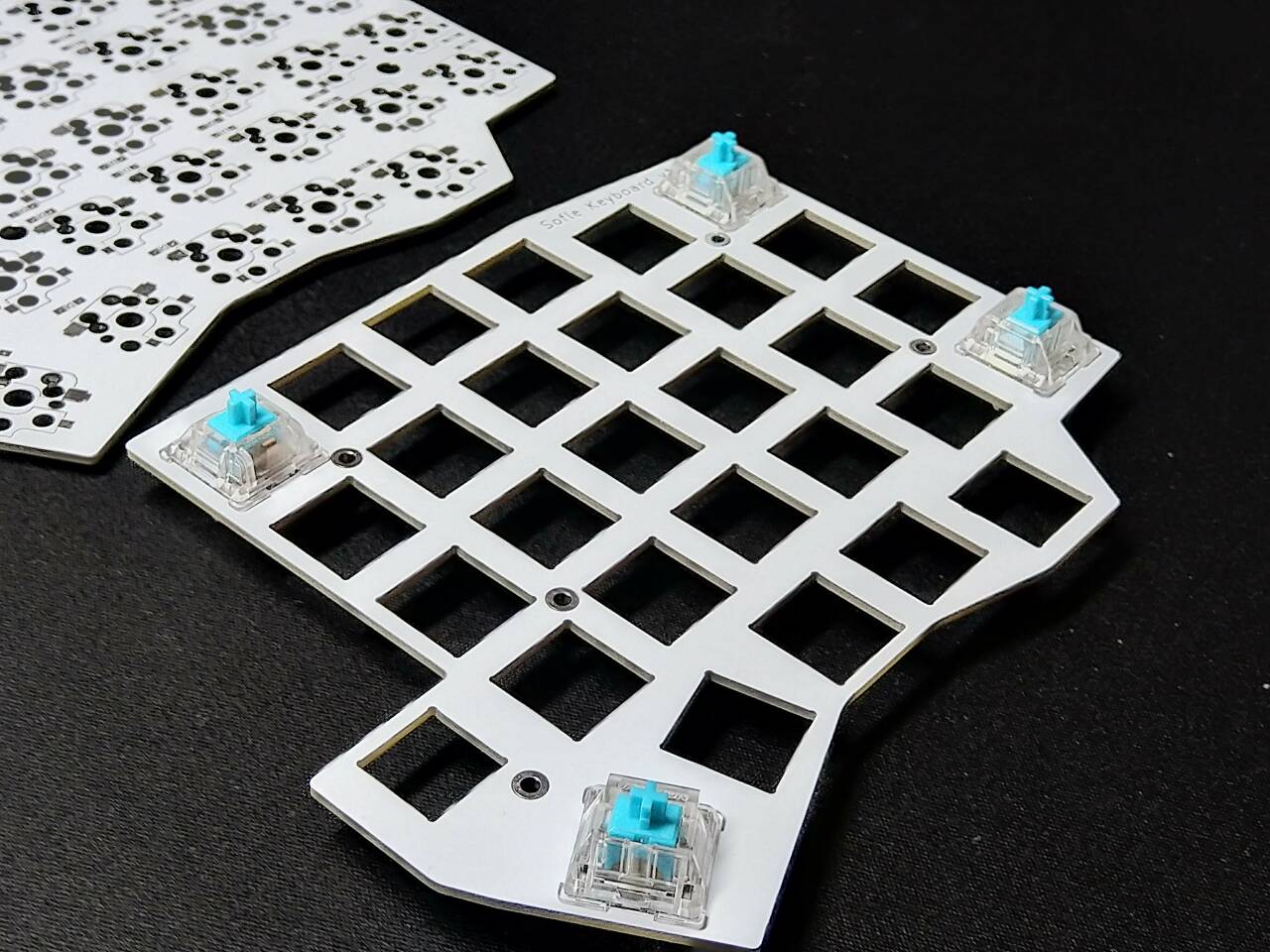
Snap first switches into corners.
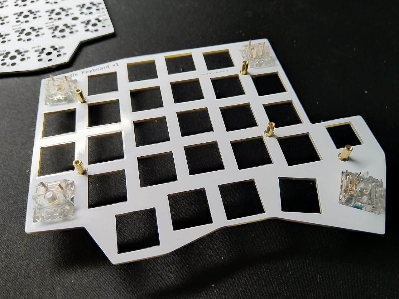
Mount the stand-offs to the top plate.
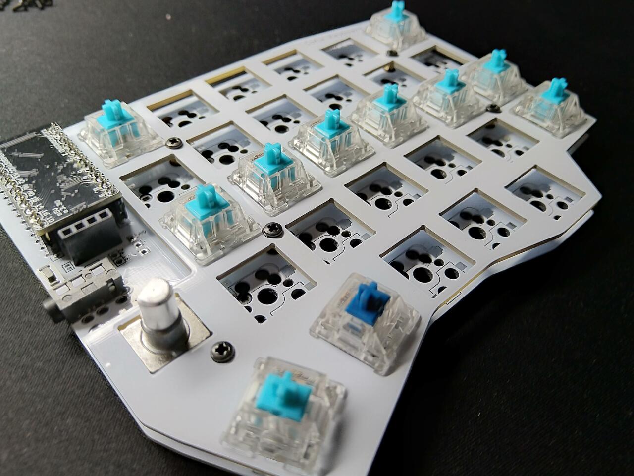
Carefully snap the first switches to the sockets. Be careful so you don’t bend their contacts. Add more.
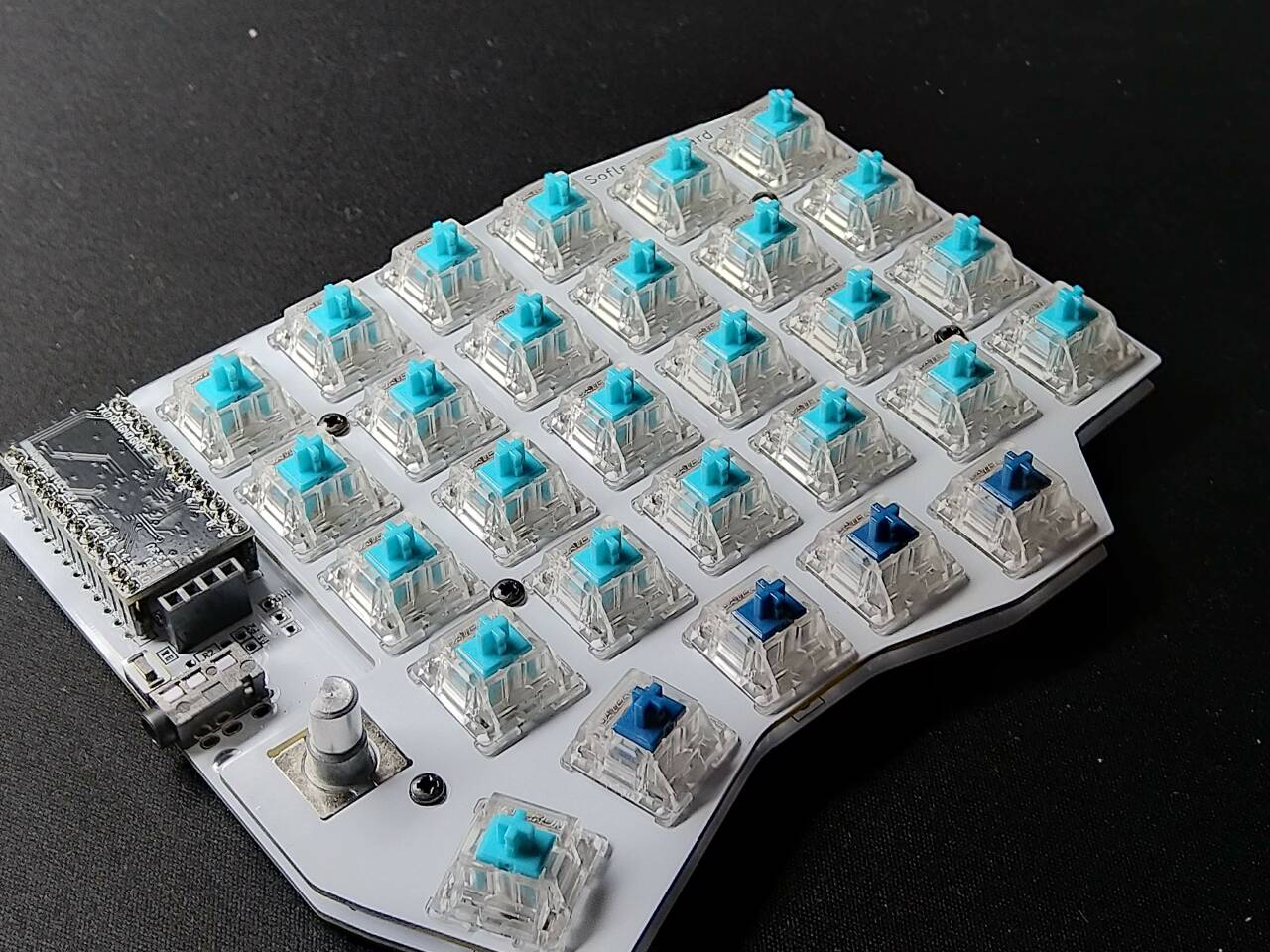
Until they are all in place.
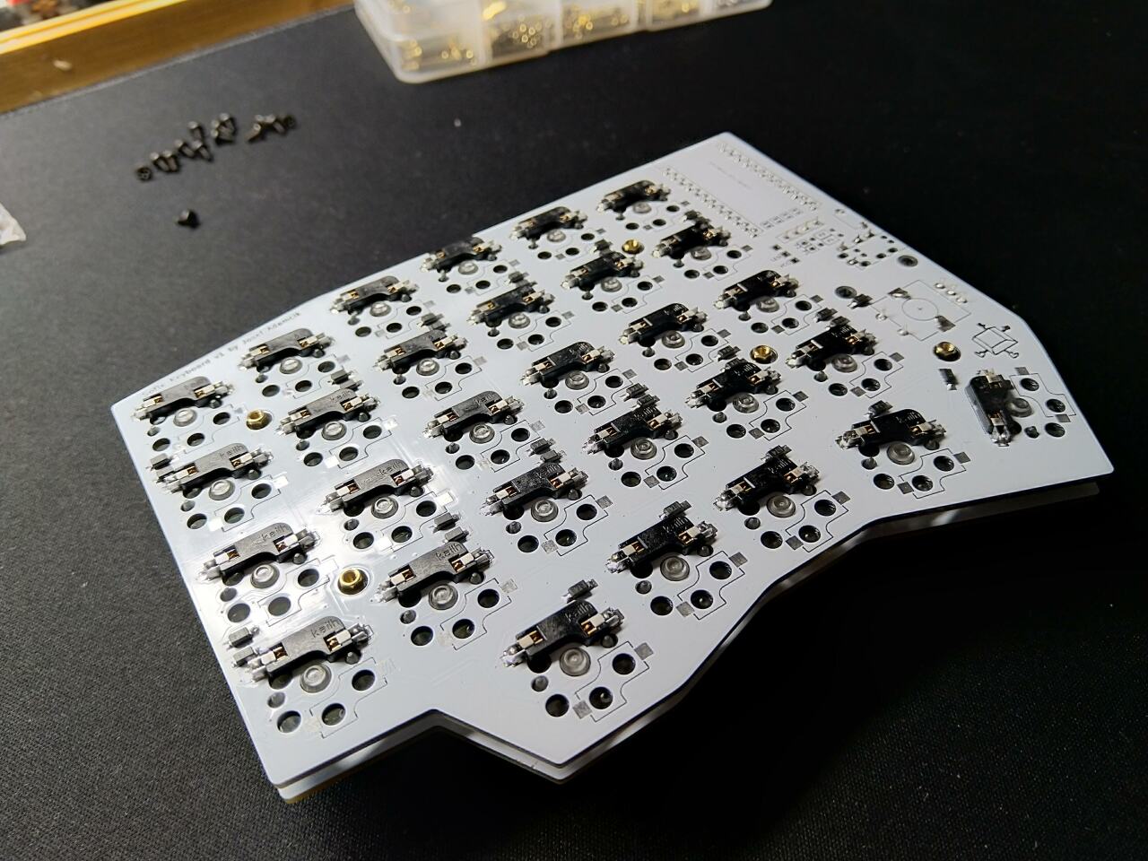
Double-check the bottom. You should see all the contacts in sockets.
And mount the bottom plate.
Completed half of the keyboard waiting for keycaps.
Finishing touches
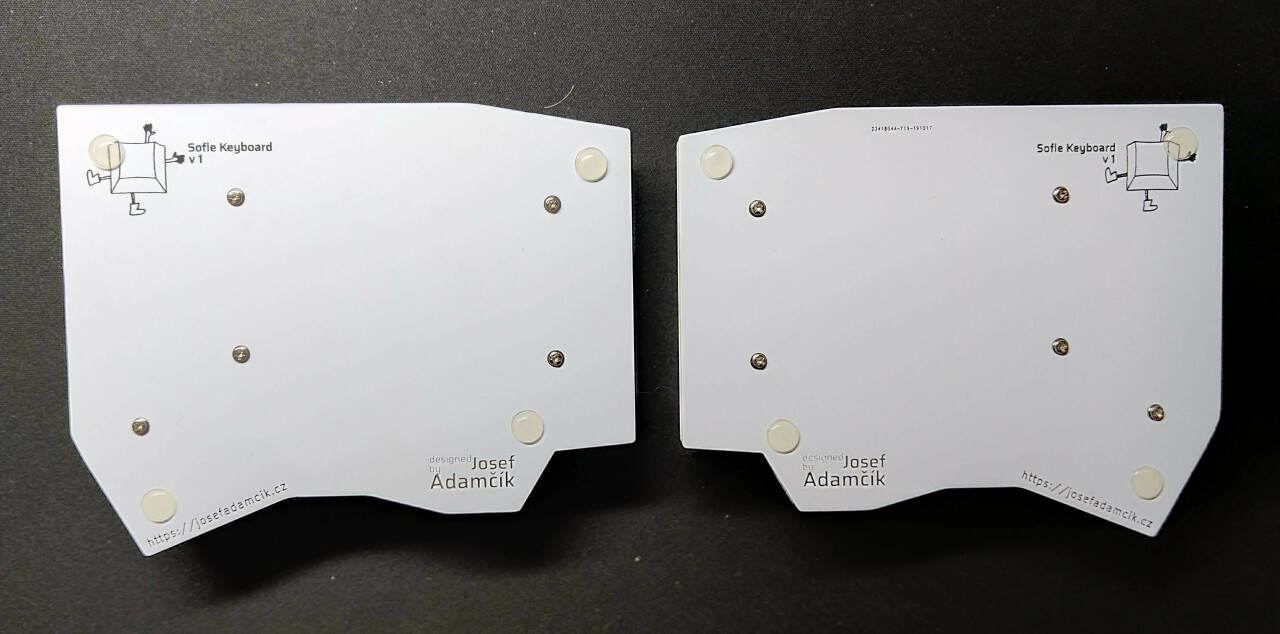
Put at least 4 adhesive rubber feet in the corners so the keyboard is not moving when you type.
Warnings and disclaimers
- Don’t connect or disconnect the TRRS cable when the keyboard is powered. It may short out. Always disconnect the USB cable first.
- Be gentle with micro USB ports on your microcontrollers. They are easy to break.
- Keep in mind that this is a prototype of a DIY keyboard. It’s not a polished product.
Firmware and programming
Sofle keyboard uses QMK Firmware and support for the board is part of the main QMK repository. There’s also a basic support in QMK Configurator but there’s no default layout yet and encoders are not supported.
Suggested approach is to build the firmware yourself. You should be familiar with QMK and be able to make it work on your local environment. If not, please follow the instructions in the documentation.
- Make sure your QMK environment is setup.
- Make sure halves are not connected together with TRRS cable.
- Connect one half to USB, flash the firmware (always follow the actuall instructions in the QMK documentation! The command might look something like this:
qmk flash -kb sofle/rev1 -km default). Use the reset button to reset the keyboard when you are asked to in console. - Connect the second half and flash it in the same way as the previous one.
- Disconnect the USB cable. Connect both halves together with TRRS cable.
- Connect USB cable to the left side2.
- Enjoy SofleKeyboard!
Troubleshooting
Elite-C v3.0
Elite-C v3.0 had problems when used with split boards (on both halves). Those are fixed in version 3.1. For v3.0 add #define SPLIT_USB_DETECT to config.h file. I don’t have Elite-C so this is untested, but should work.
Typing lag when used without OLED
If you chose to not use OLED for both halves you should disable support for oled (set OLED_DRIVER_ENABLE to no in keymaps/defualt/rules.mk).
If you don’t use OLED only on one half you are need to do one of the following to fix the lag:
- Solder pull-up resistors (4k7) to the PCB (R1, R2) without OLED.
- Use a workaround explained in this issue.
- Stop using OLED completely and turn it off as described above.
Modifications
Inverted silkscreen
If you fancy an inverted silkscreen there’s a great guide available.
Links
Footnotes
-
Serial is the default behaviour. If serial is used, you don’t need TRRS cable (4 contacts, used for headphones with a microphone) but just TRS (stereo audio jack). ↩ ↩2
-
This can be changed, look for setting handednesss in QMK documentation. ↩