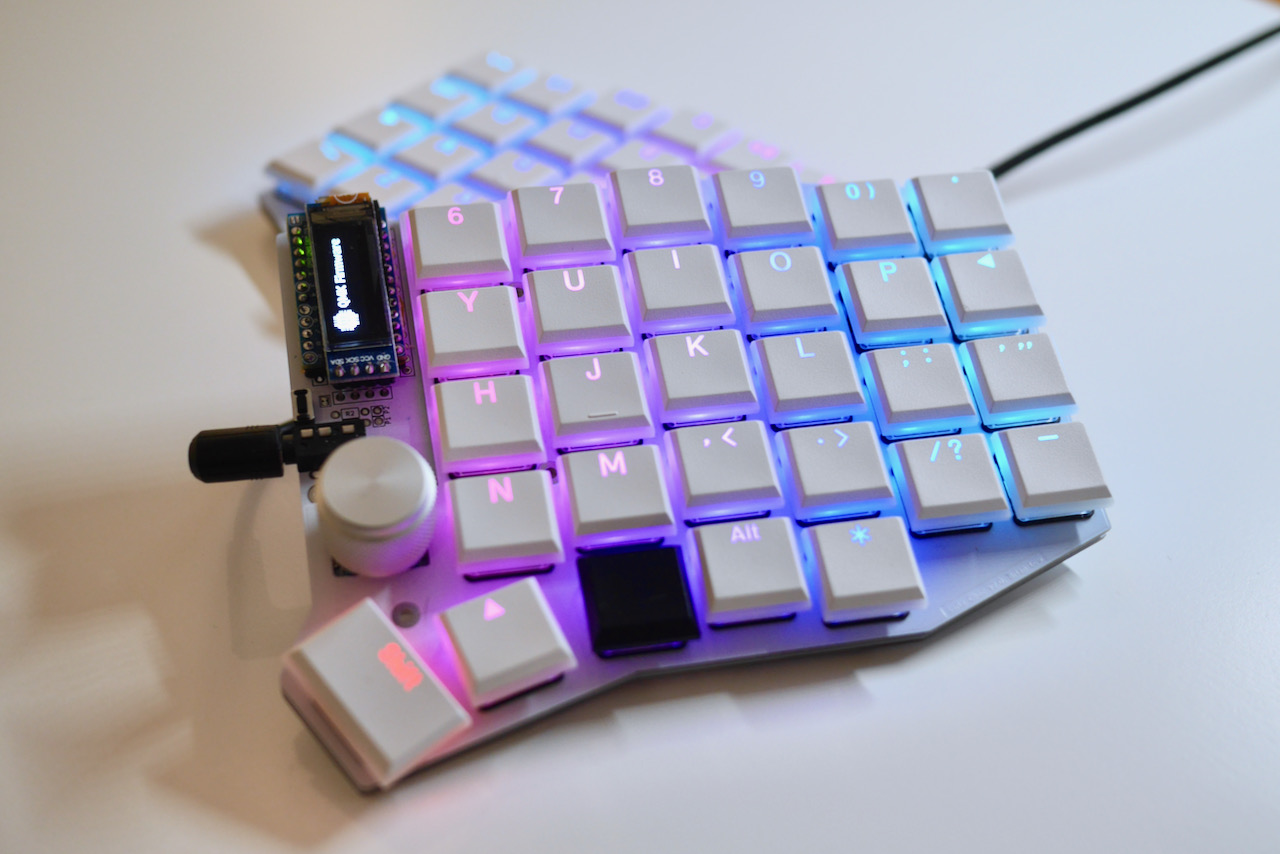
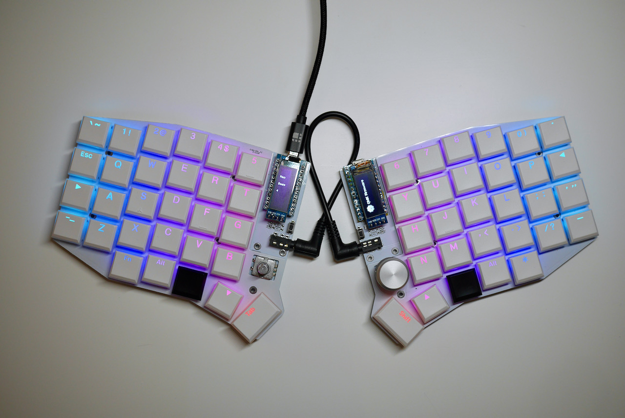
The Sofle Choc is a variation of the Sofle with:
- low-profile, Kailh Choc switches
- hotswap sockets
- per-key RGB
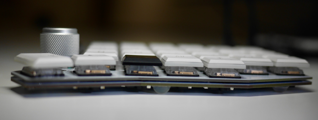
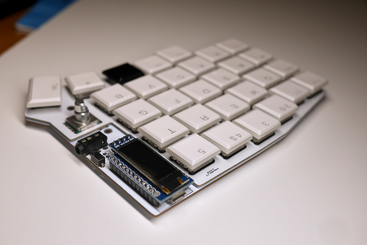
- thin, 15mm from desktop to top of keycaps
- Sofle RGB switch layout with pinky stagger in between v1 and v2
This version supports Kailh Choc v1 switches. Kailh hotswap sockets are required. Per-key RGB is optional and uses the relativey easy to solder SK6812 MINI-E LEDs.
The top plates are not compatible with Sofle v1, v2 or RGB versions. There is no bottom plate to minimize thickness.
The Sofle Choc was designed by Brian Low and based on the excellent Sofle RGB by Dane Evans which was based on the original Sofle v2 by Josef Adamčík.
Updated Build Guide and Kits
I am maintaining a newer version of the build guide and usually have kits available at:
Bill of materials
The following is needed to build the keyboard:
-
2 PCBs. Send the zip from
/Gerbers/Choc_v2/choc-v2-gerber-pcb.zipto a PCB fabrication service. The PCB should be 1.6mm thick though 1.2mm may be better. Otherwise I used JLCPCB’s default settings only customizing the PCB color. See sourcing. -
2 top plates. Send the zip
/Gerbers/Choc_v2/choc-v2-gerber-top.zipto a PCB fabrication service. The top plate holds the switches in place. The top plate should be 1.2mm thick. Otherwise I used JLCPCB’s default settings only customizing the PCB color. See sourcing. -
2 Pro Micro boards or clones. 5v, 2x12 pins, ATmega32U4 microcontroller. Don’t buy the Arduino Micro (a different pinout) or Arduino Mini (different microcontroller). You could also use Elite-C which basically Pro Micro with USB-C.
-
4x 12 pin headers (and optional sockets) for Pro Micros. There are several ways to mount Pro Micros to the board. The male pin headers you most likely got with the board can be used to solder it directly to the board. This makes it hard to replace the board if it fails. The micro-USB connector is known to tear off. I socketed the Pro Micro using the diode legs approach described at splitkb.com with two 12-pin female headers. This is the option descibed in the build guide here. Lastly, these spring pin headers are used on similar keyboards and should give a compact, non-permanent connection but have been out of stock for a long time.
-
58 Kailh Choc keyboard switches. Must be Kailh Choc v1 switches (PG1350) of any color. The
PGprefix is often omitted. Don’t buy Kailh Choc v2, Kailh Mini Choc or Cherry MX. -
58 Kailh Choc keyboard switch sockets. Sockets are specific to the PG1350 switch. The PCB requires sockets. Switches cannot be soldered directly to the board.
-
58 keycaps. You can use either all in
1usize but it looks nicer with two1.5ufor the thumb keys. -
58 diodes 1N4148W. Surface mount diodes in SOD123 package. Pick any common variation. I used
1N4148WTR(Digi-Key 1655-1360-1-ND). -
2 TRRS connectors PJ-320A. The same type which is used for Corne, Lily58 etc. Technically even TRS should work if you stick to the default serial communication.
-
2 buttons momentary, tactile, through-hole, 2 pins, I used one for DIP switches, 3x6x4.3mm. Technically optional: you can use metal tweezers whenever you need to reset the microcontroller.
-
1 TRRS cable. TRS should work if you stick with the default serial communications.
-
8 - 10 silicone bumpers. Used for feet to keep the keyboard from moving
-
Micro USB Cable to connect the keyboard to a computer.
Optional components:
- OLED/s
- 2 SSD1306 128x32 OLED display module. 4-pin, I2C, 0.91”. Very common.
- 2x 4 pin header (and optionally socket) for OLEDs. These came pre-soldered to the OLED unit. You can solder the OLED directly to the board. Ideally use a socket so you can replace and/or get at the ProMicro underneath. I found 4 pin female headers with half height (~4mm) insulation worked well
- 2 OLED covers This should be compatible with the Sofle RGB cover but have not verified
- Rotary encoders
- 2 Rotary encoders EC11. If you are not sure take EC11E. Some other variants (EC11K) may have some additional plastic pins for and require mounting holes for them which are not included on the PCB. Perfer short shaft. I used encoders with 10mm, D-shaped shaft and 30 positions from AliExpress. I also tried a high quality Bourns encoder (PEC11 series) but found it required a bit too much effort to twist.
- 2 matching knobs for each encoder. Make sure the knob matches the encoder’s shaft diameter, depth and shape.
- 2 diodes 1N4148W the encoder shafts are pushable and can be used as configurable keys.
- LEDs
- 58 SK6812 MINI-E RGB LEDs. The LED body 3.2x2.8x1.7mm and with legs is 5.8x2.8. Avoid the non-MINI-E version without the legs. Purchase extra as they are delicate. I ended up replacing 6 during my build.
- Resistors
- 2x 4.7kOhm through hole resistors These only needed if you want to use the less common I2C communication protocol between halves. They are installed in the R1/R2 spots. I have not tested an I2C setup. The firmware on this page uses serial communication and does not require the resistors.
Components that are common on other Sofle variants but are not used on this Softle Choc: bottom plate, M2 spacers and screws.
Tools and materials
- soldering iron and solder
- no-clean flux makes soldering easier
- solder wick or desoldering pump to correct mistakes
- good tweezers
- flush cutters to trim diode legs when socketing the ProMicro
- masking, kapton or electrical tape
- isopropyl-alcohol for cleaning
- screwdriver
- 1.5mm hex key for the set screw on the encoder knob
- mulitmeter for troubleshooting
Steps
Prepare
Make sure you know which side you are working on, and don’t make two left hand sides by mistake. Stick a piece of tape on the front side of both PCBs to help remember.
This guide is written in the order I like to install components.
We will start with the components on the back, shortest to tallest:
- diodes
- LEDs
- switch sockets
Then install the components on the front:
- OLED jumpers
- ProMicro & socket
- OLED & socket
- reset switch
- TRRS connector
- encoder
The order of assemby does not matter except for these 3 components because they stack on top of one another:
- the four OLED jumpers
- the Pro Micro
- the OLED screen
The build guides for the Sofle and Sofle RGB have some good tips and photos. However there are differences so use this page as your primary reference. In particular, use the ProMicro orientation described on this page.
Switch Sockets and Diodes
These components are placed on the back of the PCB.
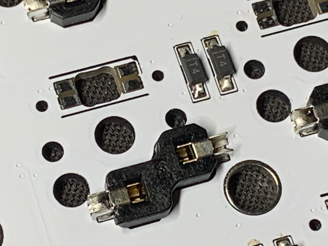
Diodes must be oriented with the white band in the direction of the “arrow” symbol on the PCB. I typically tin one pad, place the diode on, apply the soldering iron to the diode leg until it melts the solder underneath and sinks flush with the PCB. Then come back and solder the other leg.
The sockets are the largest and easiest to solder. They are installed on the back of the PCB facing up towards the front of the PCB. Make sure they are flush with the PCB. Heat the metal connector, apply solder and look for the solder to wick down to the PCB. You want a solid joint since this may take some mechanical strain from switch installation and removal.
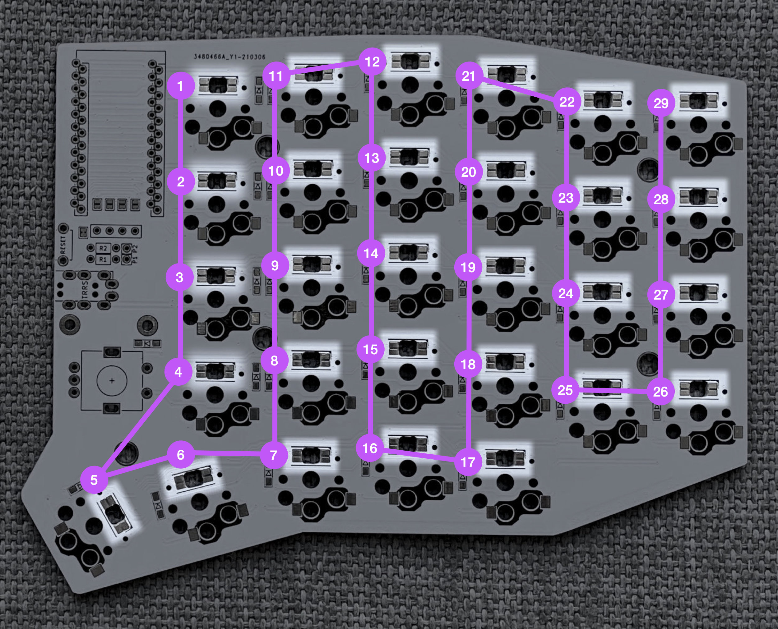
The LEDs
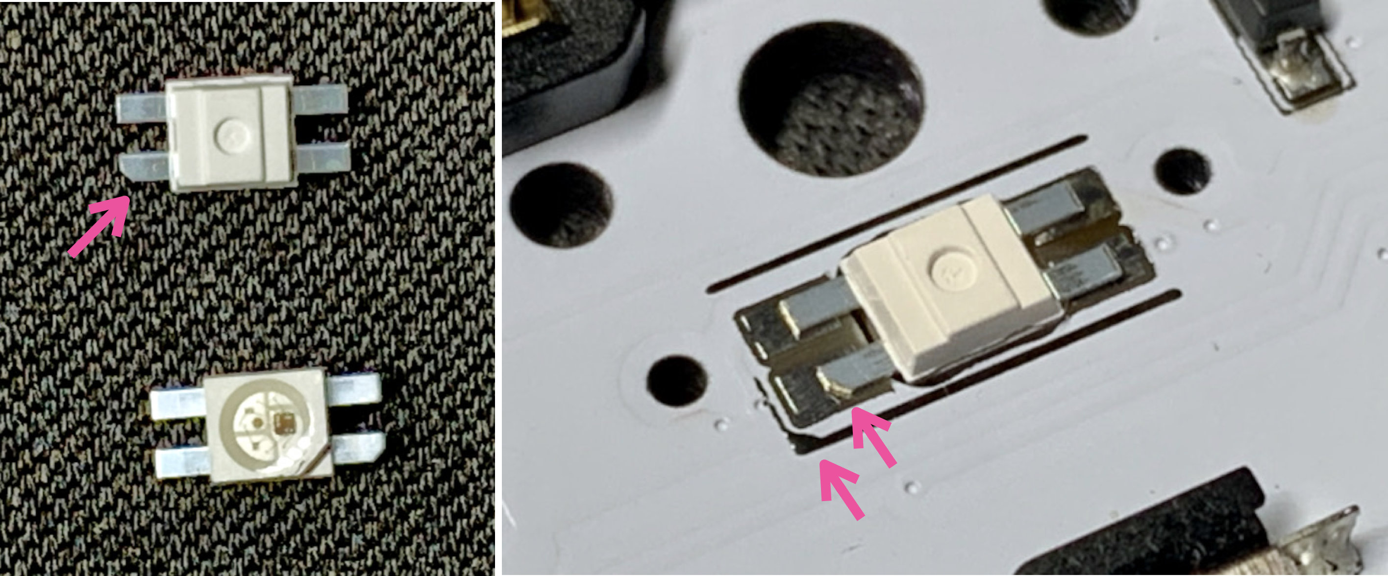
LEDs are placed on the back of the PCB. The lens should point up through the PCB so they shine into the bottom of the switch. One leg will have a diagonal cut. This cut leg should be aligned with the triangular marking on the PCB.
To solder: tin one pad, place the LED and hold using tweezers, apply heat to the leg until the solder melts and the LED is flush with the board. Now the remaining legs can be soldered without the component moving. The LEDs are sensitive to heat. Let the LED cool between soldering each leg. Use the lowest heat needed for your solder.
The LEDs are wired in one long chain. If a LED is not working, replace the LED and the LED preceeding it. Sometimes just the output of a LED is damaged. The full chain does not need to be installed if you want to test a partially built board.
OLED Jumpers
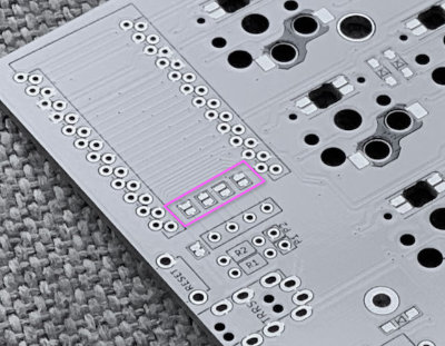
Now we move to the front of the PCB.
The jumpers in the photo should be bridged if using an OLED dispay. The jumpers may not be accessible later in the build depending on how the Pro Micro is attached. Bridge the jumpers on the top side of the board, the same side the ProMicro will be mounted on.
Pro Micro
The Pro Micro is installed on the top of the board, upside down and in the marked holes.
- Top of the board: this is the side of the PCB opposite the diodes, LEDs and switch sockets
- Upside down: both Pro Micro components should face the PCB with the mostly plain back facing out
- Marked holes: there are two sets of holes in the PCB, use the holes with the rectangular outline on the top of the board
Double-check your work here. This step is hard to reverse if a mistake is made.
To install a socketed Pro Micro using the diode leg approach from splitkb.com:
-
Install the 12-pin female headers on the top of the board in the outlined through holes. Use some tape to temporarily tack them in place. Flip the board over onto a flat, hard surface. While soldering the first pins, push down on the PCB to ensure the headers are perpendicular and fully seated.
-
Flip the board upright again. Optionally place some tape over the sockets to protect against fusing parts together. Place the Pro Micro upside down on top. Push diodes though the Pro Micro holes, through the tape and seated into the socket below.
-
Solder the legs to the Pro Micro. Snip off the legs above the Pro Micro.
If you ever need to remove the Pro Micro: do it by gently prying the board up in small increments, working your way around the board. Avoid pressure on the USB connector. The diode leags are quite weak and will usually bend if you pull the Pro Micro off in one action.
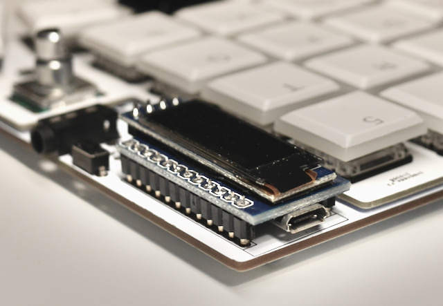
OLED
Install the OLED so it overhangs the Pro Micro. I added electrican’s tape to the bottom of the OLED module where it might contact the Pro Micro.
If you are socketing the OLED, install the 4 pin, half height female header on the top of the PCB. Then push the OLED pins into the socket. You may need to trim the OLED pins so the insulation on the female and male headers mate and the OLED sits just above the Pro Micro. The downside to socketing is the OLED isn’t as secure in the half height socket. When turning the keyboard upside down I find the OLED will lever away from the Pro Micro somewhat.
Solder misc components
Use tape to tack each component in place while flipping the board over to solder.
Solder the reset switch.
Solder the TRRS connector. You may need to bend the TRRS connector pins 90 degrees so they point down into the PCB. The R1 and R2 locations should remain empty.
Solder the encoder.
Assemble
-
Snap a few switches into the top plate, the corner switches work best
-
Place the PCB on a flat surface. This will save some strain on the solder joints in the next step (though they should be able handle it).
-
Carefully lower the top plate with switches on the main PCB and push into sockets. Ensure pins are aligned.
-
Snap the remaining switches into the top plate pressing into the sockets.
-
There are no standoff between the PCB and top plate
-
Place the encoder knob on the shaft. Tighten the set screw with a hex key. A small screwdriver for glasses may do in a pinch.
-
Optionally add oled covers
-
Put at least 4 adhesive rubber feet in the corners so the keyboard is not moving when you type.
Warnings and disclaimers
- Don’t connect or disconnect the TRRS cable when the keyboard is powered. It may short out. Always disconnect the USB cable first.
- Be gentle with micro USB ports on your microcontrollers. They are easy to break.
- Keep in mind that this is a prototype of a DIY keyboard. It’s not a polished product.
Firmware and programming
The Sofle Choc uses QMK Firmware. Support is not in the main QMK repository yet. Instead use the brianlow/qmk_firmware fork. Suggested approach is to build the firmware yourself. You should be familiar with QMK and be able to make it work on your local environment. If not, please follow the instructions in the documentation. Note QMK setup is fairly invasive (upgrade every homebrew package on your system) so you might want to consider the QMK Docker image for compiling.
To flash:
- Clone https://github.com/brianlow/qmk_firmware
- Switch to the
choc2branch withgit checkout choc2 - Make sure your QMK environment is setup.
- Make sure halves are not connected together with TRRS cable.
- Connect one half to USB, flash the firmware (always follow the current instructions in the QMK documentation! The command might look something like this:
qmk flash -kb sofle_choc -km default). Use the reset button to reset the keyboard when you are asked to in console. Some Pro Micros require double-clicking the reset button to enter bootloader mode. - Connect the second half and flash it in the same way as the previous one.
- Disconnect the USB cable. Connect both halves together with TRRS cable.
- Connect USB cable to the left side.
- Enjoy SofleKeyboard!
There is also a firmware version that uses VIA. VIA allows you to quickly change your keymap without flashing or a QMK build environment. I highly recommend it for experimenting. There are few downsides:
- it doesn’t support custom logic like a key for switching betwen Mac/Win
- the exporting/importing keymaps has some problems with some multi-chord keys though typically I don’t find I need to export/import
- lighting configuration keys only seem to affect lighting on the master side. If you don’t change lighting much, a workaround is to plug just the right side in to the computer, change the lighting then plug everrything back normally
To use the VIA firmware
- Clone https://github.com/brianlow/qmk_firmware
- Switch to the
choc-brianbranch withgit checkout choc-brian - When flashing use the
choc_briankeymap:qmk flash -kb sofle/rev1 -km choc-brian - Download the VIA app from https://caniusevia.com/, it should recognize the keyboard when it opens
Troubleshooting
See the Sofle build guide.
Links
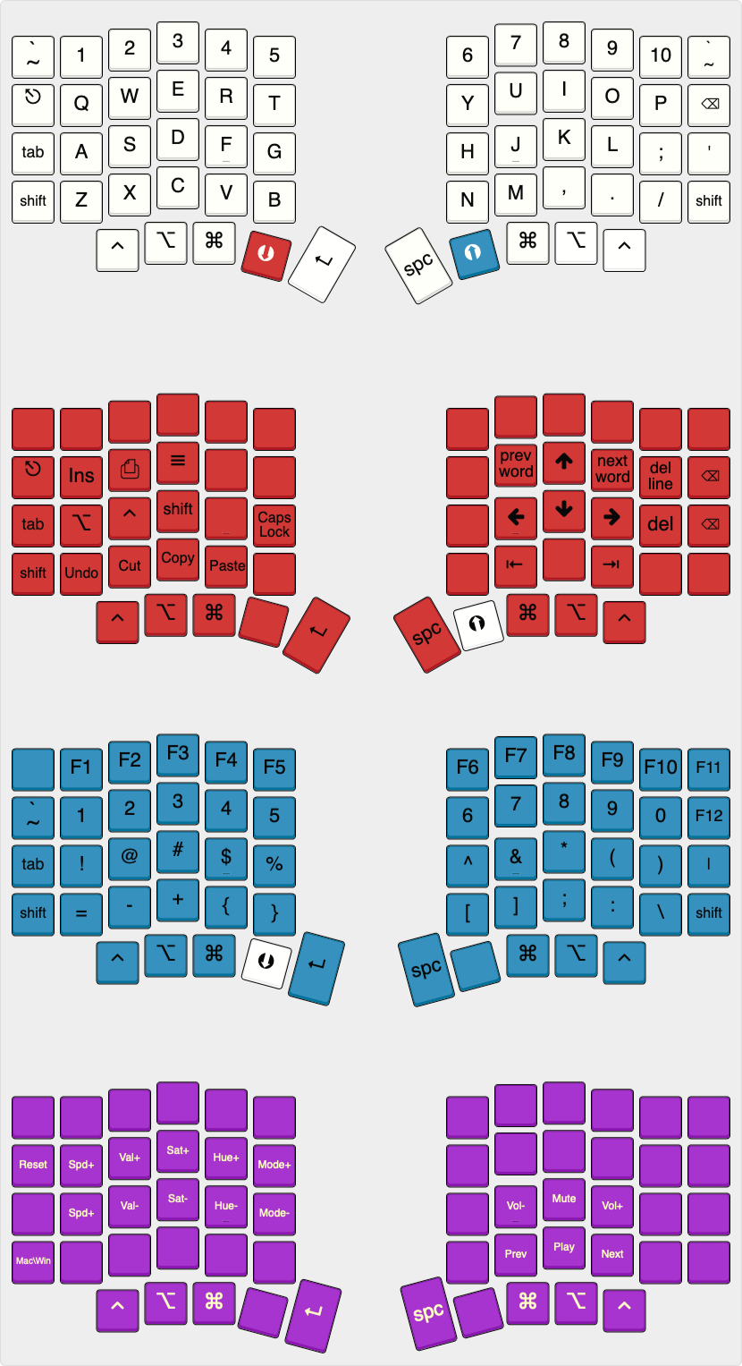
Default layout
The default layout for the Sofle Choc is in the QMK fork and demonstrates some LED functions.
Images of keyboard
Version History
- v2.1.1 - Top plate: moved the version label to less visible location, widened the area above the encoder. PCB version remains at v2.1
- v2.1 - First published version